Innovative, green industrial IoT solutions for the water and infrastructure sectors
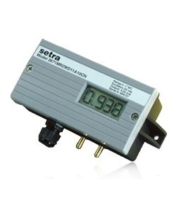
Differential Pressure Transducer
Setra’s Model 267 and 267MR Differential Pressure Transducer sense gauge (static) or differential pressure and convert this pressure difference to a proportional electrical output. The 267 series is offered with a high level voltage output or 4-20 mA current output. The 267MR offers multi-range capability and field configurable 0-5 VDC or 0-10 VDC output, as well as a 4-20 mA output.
In a typical Setra configuration, Model 267 and 267MR has a compact housing contains two closely-spaced, parallel, electrically-isolated metallic surfaces, one of which is essentially a diaphragm capable of slight flexing under applied pressure. The diaphragm is constructed of low-hysteresis material such as 17-4 PH SS or a proprietary compound of fused glass and ceramic (Setraceramâ„¢). These firmly secured surfaces (or plates) are mounted so that a slight mechanical flexing of the assembly, caused by a minute change in applied pressure, alters the gap between them (creating, in effect, a variable capacitor). The resulting change in capacitance is detected by a sensitive linear comparator circuit (employing proprietary, custom-designed ASICs), which amplifies and outputs a proportional, high-level signal.
Features / Benefits
Applications
Specifications
Features / Benefits
- Model 267MR Offers Multi-Range Capability, 6 Field Selectable Ranges via Dip Switches, and Field Selectable 0-5 or 0-10 VDC Output
- Model 267 Offers an Optional 3 1/2 Digit LCD Display with a 0.5% FS Standard Accuracy
- NEMA 4/IP65 Rated Housing
- Optional accuracy as high as 0.25% full scale
- 24 VAC or 24 VDC Excitation
- PG-9, PG13.5 or Conduit Electrical Termination
- Integral Static Pressure Probe
- Ranges as low as 0.1 in. W.C. (25 Pa)
- Meets CE Conformance Standards
Applications
Model 267 and 267MR is used in the following applications:
- Heating, Ventilating and Air-Conditioning (HVAC)
- Energy Management Systems
- Static Duct Pressure
- Clean Room Pressure
- Oven Pressurization and Furnace Draft Controls
Specifications
Technical Details
| Performance | ||
| Standard | Optional | |
| Accuracy* RSS (At Constant Temp.) | ±1.0% FS | ±0.4% FS ±0.25% FS |
| Non-Linearity, BFSL | ±0.98% FS | ±0.38% FS ±0.22% FS |
| Hysteresis | 0.10% FS | 0.10% FS 0.10% FS |
| Non-Repeatability | 0.05% FS | 0.05% FS 0.05% FS |
| Thermal Effects** | ||
| Compensated Range °F(°C) | +40 to +150 (+5 to +65) | |
| Zero/Span Shift %FS/°F(°C) | ±0.033 (±0.06) | |
| Maximum Line Pressure | 10 PSI | |
| Overpressure | 10 PSI in Positive or Negative Direction | |
| Warm-up Shift | ±0.1% FS Total | |
| Position Effect** | ||
| Range | To 0.5 in. / To 1.0 in. / To 2.5 in. / To 5.0 in. | |
| *RSS of Non-Linearity, Non-Repeatability and Hysteresis. **Units calibrated at nominal 70°F. Maximum thermal error computed from this datum. ***Unit is factory calibrated at 0g effect in the vertical position. | ||
Physical Description
| Case | Fire-Retardant Glass Filled Polyester (UL 94 V-0 Approved) | |
| Mouting | Four screw holes on removable zinc plated steel base (designed for 2.75” snap track) | |
| Electrical Connection | Screw Terminal Strip | |
| Electrical Termination | PG-9/PG13.5 Strain Relief, 1/2″ Conduit Opening, or 9 Pin D-Sub Connector* | |
| Zero and Span Adjustments | Accessible on top of case | |
| Display (Optional on 267 only) | 3 1/2 Digit LCD Integral | |
| Display | (1.74″W x 0.78″H) | |
| Pressure Fittings | 3/16″ O.D. Barbed Brass for 1/4″ Push-On Tubing (Standard) Static Pressure Probe (Optional) 1/4″ NPTF Brass (Optional) | |
| Mounting | 2 Mounting Tabs with 0.18″ Holes Pressure Probe Assembly is Supplied with a 7.8″ 6061 Aluminum Alloy Probe and a Gasket to Seal Against the Duct | |
| Weight (Approx.) | 9.0 ounces (255 grams) 9.5 ounces (Duct Probe Assembly) | |
| *9 pin D-sub Connector is not suitable for NEMA4/IP-65 environments. | ||
Electrical Data (Voltage)
| Circuit | 3-Wire (Exc, Gnd, Sig) Protected from Miswiring | |
| Excitation (for 0-5 VDC Output) | 9 to 30 VAC/12 to 40 VDC | |
| Excitation (for 0-10 VDC Output) | 11 to 30 VAC/13 to 40 VDC | |
| Model 267 | ||
| Output* | 0 to 5 VDC** 0 to 10 VDC** | |
| Model 267MR | ||
| Output* (Field Selectable) | 0 to 5 VDC** 0 to 10 VDC** | |
| Bidirectional Output at Zero | Mid-Range of Specified Output | |
| Output Impedance | 100 Ohms | |
| Re-Ranging (267MR only) | 5 Position Dip Switches (Located Inside Case) | |
| *Calibrated into a 50K ohm load, operable into a 5000 ohm load or greater. **Zero output factory set to within ±50mV (±25 mV for optional accuracies). Span (Full Scale) output factory set to within ±50mV. (±25 mV for optional accuracies). | ||
Electrical Data (Current)
| Circuit | 2-Wire Protected from Miswiring | |
| Output* | 4 to 20 mA** | |
| Bidirectional Output at Zero | 12 mA | |
| External Load | 0 to 800 Ohms | |
| Minimum loop supply voltage (VDC) = 9 + 0.02 x (Resistance of receiver plus line). Maximum loop supply voltage (VDC) = 30 + 0.004 x (Resistance of receiver plus line). Re-Ranging (267MR only) 4 Position Dip Switches (located inside case) | ||
| *Calibrated with a 24 VDC loop supply voltage and a 250 ohm load **Zero output factory set to within ±0.16mA (±0.08 mA for optional accuracies) Span (Full Scale) output factory set to wtihin ±0.16mA (±0.08 mA for optional accuracies) | ||
Pressure Media
| Typically Air or Similar Non-Conducting Gases |
Environmental Data
| Temperature | ||
| Operating* °F (°C) | 0 to +150 (-18 to +65) | |
| Storage °F (°C) | -65 to +180 (-54 to +82) | |
| *Operating temperature limits of the electronics only. Pressure media temperature may be considerably higher or lower. | ||
Note: Specification are Subject to change without notice
Request for a Quote
Complete the form below to get your free quote
Get in Touch with us at (+65) 6553 0366 / info@flotech.com.sg
Download Catalogue
Fill out the form below to download the catalogue.